Overview
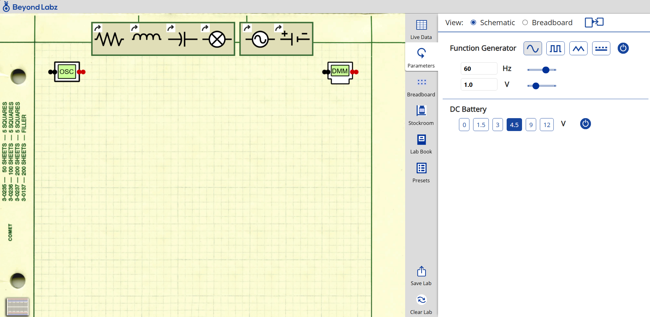
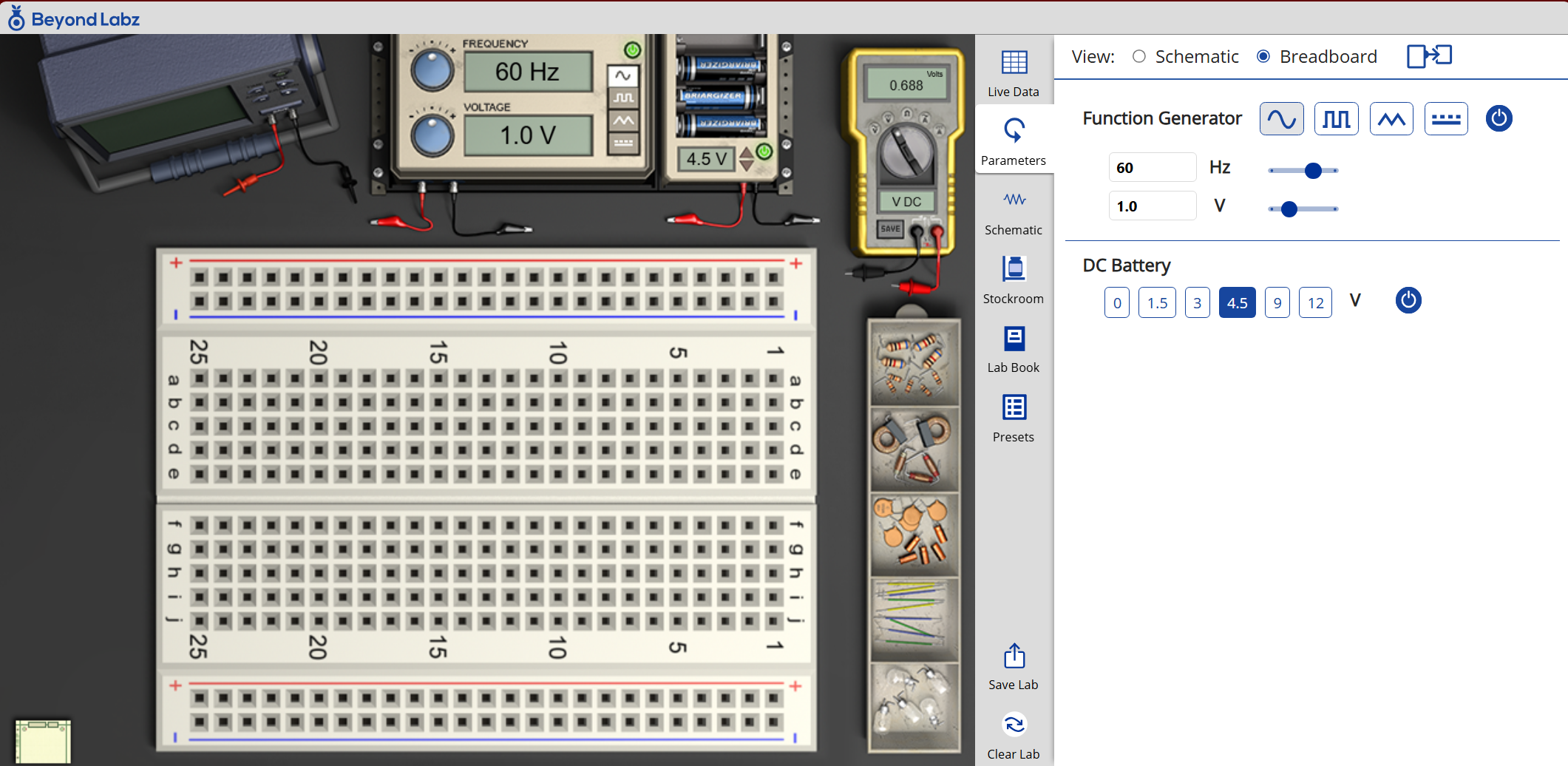
The circuit laboratory gives students the freedom to discover and learn the principles associated with simple electrical circuits involving resistors, capacitors, and inductors. The laboratory allows students to build circuits using either a breadboard or schematic representation. Using the breadboard students will connect components as they would in an ordinary circuit laboratory by adding resistors, light bulbs, capacitors, or inductors of any combination and a battery or function generator. When using the schematic, the students can “draw” a circuit schematic on paper as they would to plan a circuit. The breadboard and schematic are linked together so they automatically populate when the other one is changed. Using the digital multimeter and oscilloscope students can then analyze their circuits and learn principles like Ohm’s Law, the power-voltage relationship, AC/DC sources, and much more.